In engineering, tolerance is the allowable limit or limits of variation in any dimension. Dimensional features can vary in practice without a significant effect on part function and performance. Tolerances define reasonable deviations that can be allowed without compromising performance.
Dimensional Tolerances (ISO)
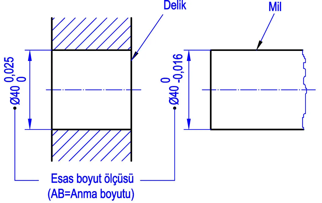
Tolerances applied to dimensional measurements, consisting of upper and lower deviation limits. The basis for selecting deviations is the nominal dimension.
ISO Hole Tolerances (ISO 286-2)
The following tables show deviation values in µm (micrometers) for the most commonly used hole tolerance classes. Upper value shows maximum deviation, lower value shows minimum deviation.
H7 Hole Tolerances (Most Common)
| Nominal Dia. (mm) | 3-6 | 6-10 | 10-18 | 18-30 | 30-50 | 50-80 | 80-120 | 120-180 | 180-250 | 250-315 | 315-400 |
|---|---|---|---|---|---|---|---|---|---|---|---|
| H7 (µm) | +12 0 | +15 0 | +18 0 | +21 0 | +25 0 | +30 0 | +35 0 | +40 0 | +46 0 | +52 0 | +57 0 |
Other Common Hole Tolerances
| Tolerance | 3-6 | 6-10 | 10-18 | 18-30 | 30-50 | 50-80 | 80-120 | 120-180 | 180-250 |
|---|---|---|---|---|---|---|---|---|---|
| E7 | +32 +20 | +40 +25 | +50 +32 | +61 +40 | +75 +50 | +90 +60 | +107 +72 | +125 +85 | +146 +100 |
| F7 | +22 +10 | +28 +13 | +34 +16 | +41 +20 | +50 +25 | +60 +30 | +71 +36 | +83 +43 | +96 +50 |
| G7 | +16 +4 | +20 +5 | +24 +6 | +28 +7 | +34 +9 | +40 +10 | +47 +12 | +54 +14 | +61 +15 |
| H6 | +8 0 | +9 0 | +11 0 | +13 0 | +16 0 | +19 0 | +22 0 | +25 0 | +29 0 |
| H8 | +18 0 | +22 0 | +27 0 | +33 0 | +39 0 | +46 0 | +54 0 | +63 0 | +72 0 |
| H9 | +30 0 | +36 0 | +43 0 | +52 0 | +62 0 | +74 0 | +87 0 | +100 0 | +115 0 |
ISO Shaft Tolerances (ISO 286-2)
Common Shaft Tolerances
| Tolerance | 3-6 | 6-10 | 10-18 | 18-30 | 30-50 | 50-80 | 80-120 | 120-180 | 180-250 |
|---|---|---|---|---|---|---|---|---|---|
| f6 | -10 -18 | -13 -22 | -16 -27 | -20 -33 | -25 -41 | -30 -49 | -36 -58 | -43 -68 | -50 -79 |
| f7 | -10 -22 | -13 -28 | -16 -34 | -20 -41 | -25 -50 | -30 -60 | -36 -71 | -43 -83 | -50 -96 |
| g6 | -4 -12 | -5 -14 | -6 -17 | -7 -20 | -9 -25 | -10 -29 | -12 -34 | -14 -39 | -15 -44 |
| h6 | 0 -8 | 0 -9 | 0 -11 | 0 -13 | 0 -16 | 0 -19 | 0 -22 | 0 -25 | 0 -29 |
| h7 | 0 -12 | 0 -15 | 0 -18 | 0 -21 | 0 -25 | 0 -30 | 0 -35 | 0 -40 | 0 -46 |
| js6 | +4 -4 | +4.5 -4.5 | +5.5 -5.5 | +6.5 -6.5 | +8 -8 | +9.5 -9.5 | +11 -11 | +12.5 -12.5 | +14.5 -14.5 |
| k6 | +9 +1 | +10 +1 | +12 +1 | +15 +2 | +18 +2 | +21 +2 | +25 +3 | +28 +3 | +33 +4 |
| n6 | +16 +8 | +19 +10 | +23 +12 | +28 +15 | +33 +17 | +39 +20 | +45 +23 | +52 +27 | +60 +31 |
| p6 | +20 +12 | +24 +15 | +29 +18 | +35 +22 | +42 +26 | +51 +32 | +59 +37 | +68 +43 | +79 +50 |
Fits
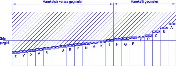
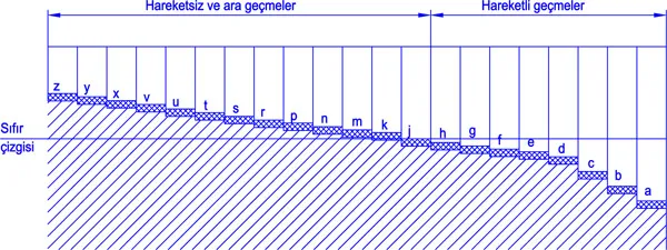
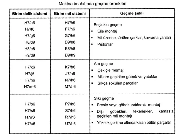
A fit defines the dimensional relationship between a shaft and a hole. The ISO system defines three basic fit types:
1. Clearance Fit
The shaft is always smaller than the hole. There is always clearance between the parts. The shaft can move freely within the hole.
- H7/f6 — Sliding fit. Rotating shafts, plain bearings
- H7/g6 — Close sliding fit. Precision sliding parts
- H8/f7 — Loose running fit
- H9/e9 — Free running fit
2. Transition Fit
Shaft and hole dimensions may overlap. Assembly may result in either clearance or interference. Used for locating and alignment applications.
- H7/js6 — Light transition fit
- H7/k6 — Medium transition fit. Pin and bushing assembly
- H7/m6 — Tight transition fit
3. Interference Fit
The shaft is always larger than the hole. Force or heat is required for assembly. Parts are tightly connected to each other.
- H7/n6 — Light interference fit. Precision location
- H7/p6 — Medium interference fit. Permanent assembly
- H7/r6 — Heavy interference fit. Heavy loads
ISO Fits Used in Mechanical Engineering
| Fit Type | Hole / Shaft | Application Area |
|---|---|---|
| Free running | H8/e8, H9/d9 | Loose rotating parts, long bearings |
| Sliding | H7/f6, H8/f7 | Rotating shafts, plain bearings |
| Close sliding | H7/g6 | Precision positioning, sliding pins |
| Transition | H7/js6, H7/k6 | Gear hubs, pin assembly |
| Light press | H7/n6, H7/p6 | Bushing, ball bearing assembly |
| Press | H7/r6, H7/s6 | Permanent connections, heavy loads |
Note: This article contains the most commonly used tolerance classes. Complete ISO 286-2 tables cover all hole tolerances from E6 to P8 and all shaft tolerances from e6 to s7.
Related Articles
Translated by: Yamac Aksan. Source: ISO 286-2